|
That’s one big model!
A VERY BRIEF HISTORY LESSON
The Saturn V was the ultimate
development in manned expendable rockets by the United States of America. It was
the culmination of years and years of research and experimentation, with the V2
rocket of WW2 as one of its direct ancestors, both having been designed by a
team of engineers led by Dr Wernher Von Braun. The Saturn V was designed to send
a team of astronauts and their equipment to the moon and return them safely to
earth.
The model depicted here is the sixth
Saturn V to fly, SA-506, more famously known as Apollo 11. Saturn V missions and
their launch dates were as follows:
SA-501/Apollo 4,
9 October 1967 (unmanned)
SA-502/Apollo 6,
4 April 1968 (unmanned)
SA-503/Apollo 8,
21 December 1968 (Borman, Lovell, Anders)
SA-504/Apollo 9,
3 March 1969 (McDivitt, Scott, Schweickart)
SA-505/Apollo 10,
18 May 1969 (Stafford, Young, Cernan)
SA-506/Apollo 11,
16 July 1969 (Armstrong, Collins, Aldrin)
SA-507/Apollo 12,
14 November 1969 (Conrad, Gordon, Bean)
SA-508/Apollo 13,
11 April 1970 (Lovell, Swigert, Haise)
SA-509/Apollo 14,
31 January 1971 (Shepard, Roosa, Mitchell)
SA-510/Apollo 15,
28 June 1971 (Scott, Worden, Irwin)
SA-511/Apollo 16,
16 April 1972 (Young, Mattingly, Duke)
SA-512/Apollo 17,
7 December 1972 (Cernan, Evans, Schmitt)
SA-513/Skylab 14,
May 1973 (Unmanned)
HISTORY
OF THE MODEL
Around 9 years ago I first began
discussions with the staff of the Sir Thomas Brisbane Planetarium about building
a number of scale models for display in their foyer. Many of these centred
around the Apollo moon missions. One of the dreams they had was for a very large
and impressive Saturn V, with 1/48 being the obvious scale of choice, as ceiling
limitations prevented even larger scales. (1/32 having briefly been considered
owing to the availability of the Monogram Apollo CSM kit.) First of the
series of models for the Planetarium though were some common kits (Though these
ended up being major rebuilds and super detailing!) such as the 1/48 Monogram
Lunar Lander, and 1/32 Monogram Apollo CSM; with some not so common kits
such as the Lunar Models 1/20 Lunar Rover and Real Space Models
Lunar Prospector.
PREPARING
TO BUILD
Having most of the tubes, spare
parts and Revell kit already in storage my first step of course was to
undertake a little research. This came readily to hand, as I have a good
selection of spacecraft books, and of course the David Weekes plans.
|
Click on
image below to see larger image
|

|
|
Plans,
kit, and many books and magazines! Did I say a little research?
|
|
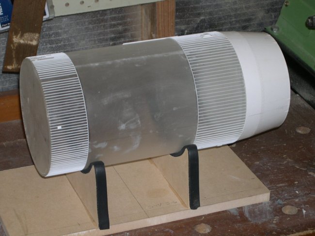
Following
an initial dry run with the tubes, I built 2 jigs to enable me to assemble the
model horizontally. The jigs comprised a series of circular templates lined with
rubber insulation to prevent slipping and scratching.
|
Click on
images below to see larger images
|
|
 |
| Main
Horizontal Assembly Jig
|
Third
Stage Horizontal Assembly Jig (with 3rd Stage in place) |
F-1 ENGINES
One of the first elements I put my
thoughts to constructing for the model were the first stage F-1 engines. These
monsters generated 1 500 000 lb of thrust each! I have seen slow motion footage
of these operating, and all I can say is RAW POWER!! Obviously, they are a
complex mechanism, and with that huge engine bell it was going to be a challenge
to build, or so I thought!
Armed with a scale cross sectional
drawing, I went in search of an appropriate plastic wine glass from a discount
retail store. Unbelievably in the very first store I went into, the very first
wine glass I picked up was a perfect match for the engine bell, and I do mean a
perfect match! Not only that, at $1.50ea I was looking at a bargain. Off I went
back to my workshop with 5 F-1 engine bells, with the intention to slowly
assemble the five engines as I progressed with the main body of the rocket. I
felt by doing this, I would be able to break up the monotony of adding all that
ribbing on the rocket body. First though, I quickly did a dry run with the five
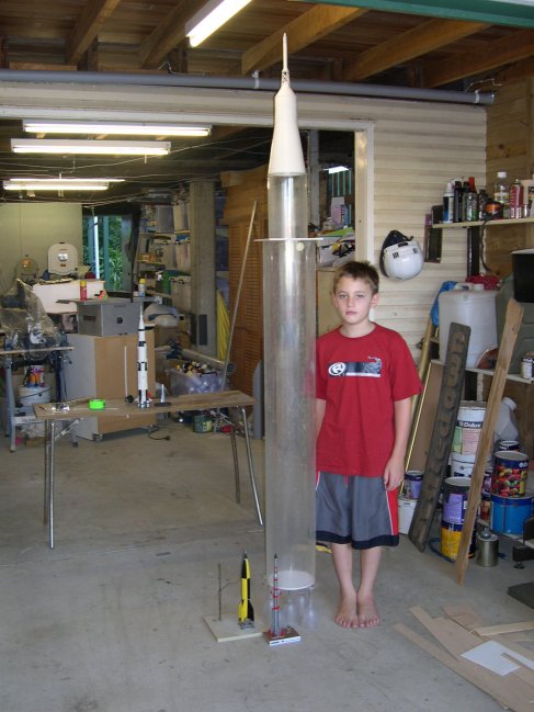
wine glasses and a quick stack of the acrylic body tubes and Apollo CSM kit.
Things were already looking tall!
 |
|
First
Dry Run – This is going to be a tall order! |
|
That’s my 11-year old son Michael standing next to the
first dry run (in the photo above).
You may note a few things in the photograph
to the right – the 1/200 AMT
Saturn V on the table, a 1/48 V-2 (Mauve kit) and my first scratch-built rocket,
a 1/48 Lambda L-4S (Japan’s first satellite launcher) at the base of the
Saturn V, which incidentally was my second scratch-built rocket!
|
Click on
image below to see larger image
|
 |
|
1/48 V-2 and
Lambda 4S rockets in comparison to the F-1 Engines
|
|
Once I began work on the first F-1
engine I realized my folly, and decided to get a mould made and cast a complete
set of engines. This would not only save me time (which I lacked!), but also
meant I could put a bit more effort into the one master. Building up the ribbing
etc was a simple matter of using Evergreen strip and rod, and also automotive
body filler. Though the flight engines were wrapped in foil insulating blankets,
the ribbing and plumbing was still noticeable through the blankets. I simply
duplicated the originals by building the engine, and its main plumbing, then
covering them in aluminium foil pieces. Engine plumbing was a combination of
parts from my spare parts box and sprue runners from an Academy B-50 model kit.
(Perfect for diameter and radius bends.)
|
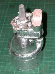
The completed master, once foiling
was completed looked very convincing. (See below). The cut-off stem of the
wineglass was deliberately left long, as it provided a very strong mating
point to the model, as well as a good pour section for casting.
|
Click on
image below to see larger image
|
 |
|
Scaledown
1/48 F-1 engine
master with a Revell 1/96 F-1 engine.
|
|
| It was now off to OZMODS with the
completed master for the casting to begin. The end result, prior to
painting can be seen below. The final engines were spray painted with
acrylic lacquer automotive paint and then detail painting with Humbrol
enamels finishing them off. |
|
Click on
image below to see larger image
|
 |
 |
|
The
foiling completed!
|
|
EXTERNAL
DETAILING
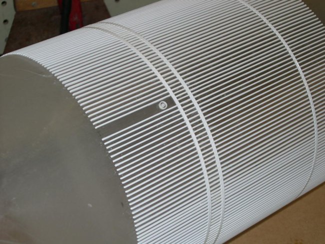
The stages of the Saturn V have several
areas covered in ribbing. This ribbing forms the reinforcing for the areas not
containing a pressurised fuel tank. David Weekes set of drawings (10 in all) is
invaluable in detailing the Saturn V. The ribbing is extremely numerous and is
composed of differing sizes, and here
Scaledown’s
stock of Evergreen stripping
proved exhaustible! Fortunately the sizes I required were in stock and promptly
ordered from the wholesaler. I could not possibly fathom the cost of this had I
had to pay retail!
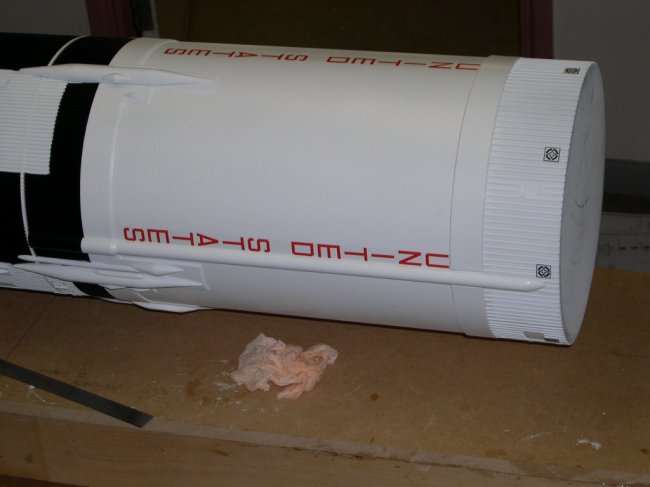
The external detailing also included a
number of fuelling and electrical umbilical attachment points. These were
scratch-built using sheet styrene, Evergreen strip and tube, and spare parts.
Locating the appropriate points accurately on the stage proved an easy exercise,
as I labelled the stages identically to NASA. (See photo) This is in the form of
Roman numerals i, ii, iii, iiii and the letters A, B, C, D. These are clearly
marked on the David Weekes plans. Further up the rocket, it then translates into
+X, -X, +Y, and –Y co-ordinates for the Lunar Module and CSM sections.
Other details such as the F-1 engine shroud
attachment points were scratch-built using more Evergreen strip.
|
Another feature of the Saturn V
are the various fairings that adorn the interstage areas of the main body.
I decided to mould several of these, as there were up to five units to be
made.
|
Click on
image below to see larger image
|
 |
|
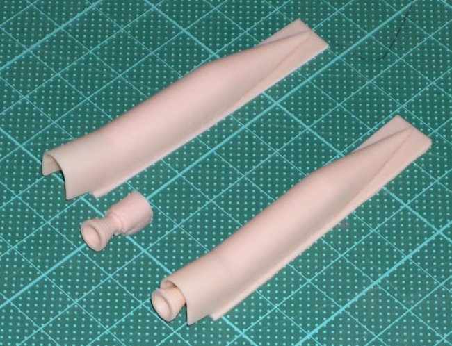
I also took the opportunity to mould the ullage rocket
units, of which four appear on Apollo 11. Early Saturn V’s had 8 of these
motors (see the AMT kit which feature all 8!), and later Saturn V’s actually
deleted these, as they were considered unnecessary. Their omission assisted in
increasing the weights of later missions.
|
Click on
images below to see larger images
|
 |
 |
|
Some of the individual
castings made for this project.
(Now available from
Scaledown as Set SDA48056:
Saturn V Detail Set.) |
Close up of the
Ullage motor units. The rocket nozzle (Modified from a 1/288 Shuttle
engine) fits neatly into a pocket in the fairing.
|
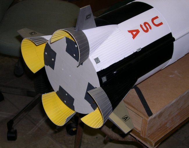
3rd STAGE INTERSTAGE
This section of the rocket is a
truncated cone shape. I built this by constructing two acrylic circular plates
with acrylic supports in between. The two acrylic circles corresponded to the
diameters of the 2nd and 3rd stages. I then glued a
section of 0.5mm styrene sheet to the outside of these, with Evergreen ribbing
providing additional detailing and rigidity. As you can imagine, with only a
thin wall this section if man-handled (as I had been the other sections) would
have been irreparably damaged. I placed two brass tubes through this unit (One
centred, the other offset) for ease and strength in reassembly. I needed to do
this, as the model is transported in several sections, and then slides together
for final assembly.
|
Click on
images below to see larger images
|
 |
 |
| Interstage unit part
way through adding the ribbing. Note the offset brass tube locators. |
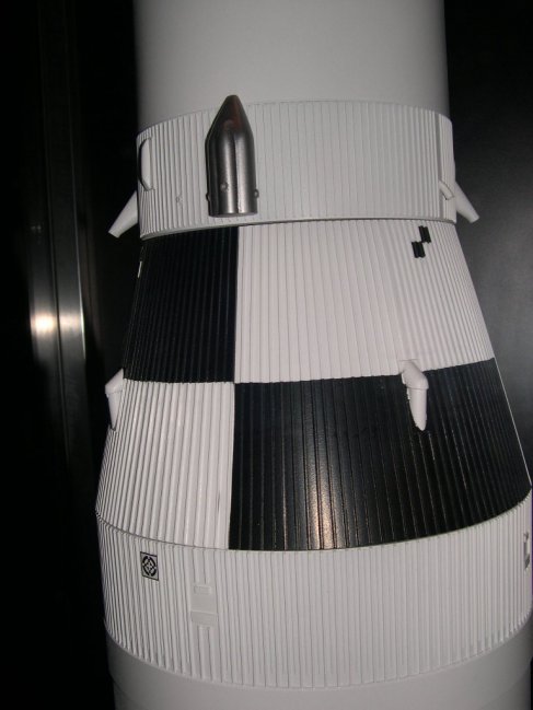
The
finished Interstage, complete with four retro-rocket fairings. Note the
photographic targets on the 2nd Stage. These were part of the
superb custom decal sheet produced for me by Steve Evans of Hawkeye
Decals. |
F-1 ENGINE
FAIRINGS
I at first avoided even thinking about how I was
to build these units, as I had so much on my mind. Finally, when I could avoid
it no longer, I opted to build all four individually, rather than make one and
cast it. I began again by using the David Weekes plans, which
have a flat pattern of these units. I built mine using 0.5mm sheet styrene cold
rolled into the cone shape, trial fitting the first one to confirm I had the
right shape. Only a slight amendment was required from the pattern provided in
the plans. See below
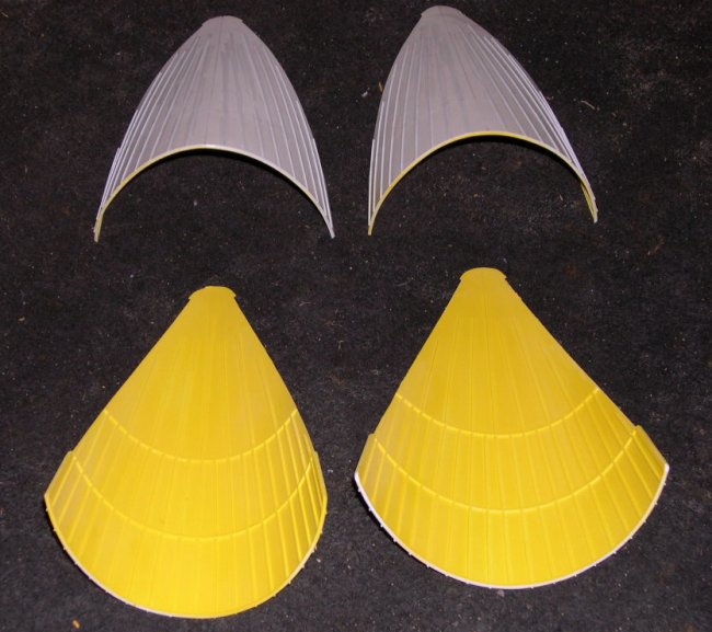
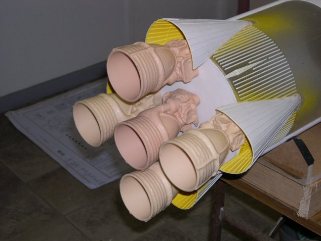
| I then applied curved Evergreen strips on
both sides of the sheet to reinforce this curve. I was very happy with the
end result. I painted the interior a chromate yellow primer, based on some
references I had, though other sources showed it to be aluminium in colour.
I will let the pedantic rivet/FS Number counters to argue that one, but I
felt the yellow looked more interesting anyway! |
Click on
image below to see larger image
|
 |
|
Initial trial fitting.
The ribbing is yet to be added.
|
|
APOLLO
COMMAND SERVICE MODULE
This began life as the Revell 1/48 Apollo CSM
kit. This was greatly modified to correct a number of deficiencies and
inaccuracies in the original kit. (Based on the Block 1 Apollo
spacecraft.) The entire surface of the Service Module was sanded smooth,
with styrene sheet and Evergreen being used to reproduce the details of
the Block II module.
|
Click on
image below to see larger image
|
 |
|
Lots of plastic strip,
rescribing, puttying and sanding to get to this!
|
|
The Command Module was covered in Evergreen scrap to build
up a surface for the Boost Protective Cover. Much sanding and puttying later, I
had a convincing Command Module ready for painting. Modellers take note, the
engine bell for the Service Module has incorrect details, but I left this item
out, as once assembled, you can’t see it.
The Launch Escape Tower was used straight from the kit initially,
however, with four hours to go before delivery, the lattice tower was destroyed
beyond repair when I inadvertently bumped the base of the model during some
final brush painting. The entire CSM assembly toppled off the model, pulverising
the tower on impact. Oh the tragedy!!!!!!!!!
I desperately gathered many, many pieces to attempt a reassembly, but
alas, one hour into that task I realized I hadn’t made a full recovery. Blow
this, I then went to the drawings and scratch built a new unit. Speed modelling!
|
Click on
images below to see larger images
|
 |
 |
| Apollo CSM Boost
Protection Cover from above. |
Finished CSM and Tower
atop the rocket. This is the second Launch Escape Tower made for the
model, following the demise of the first one. (see text!) |
DISPLAY
BASE
I wanted to enhance the overall impression of the
model with a base that resembled the launch pad. The real pad was rectangular in
shape, and included the support tower. I elected to model a stylised launch pad,
square in shape to fit into a custom display case that was being made for the
model. The support tower was omitted both for sanity
reasons and practicality (It wouldn’t fit!). I have seen one made in 1/33
scale by a modeller from the US. That model now resides at the
Smithsonian.
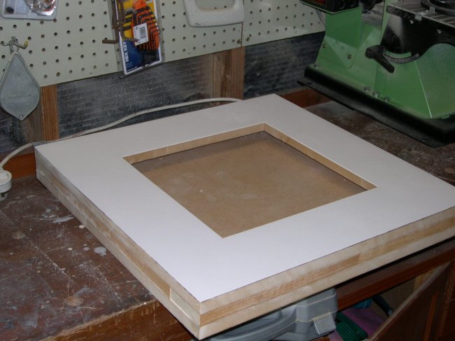
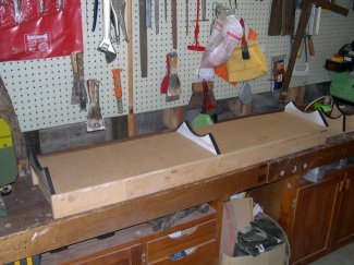
The most critical criteria for the base
was that it needed to support the rocket and prevent the rocket toppling over.
Weight saving was definitely not an issue. I laminated several pieces of 18mm
MDF board together, two of which had a square section removed from the middle to
allow for the F-1 engines to sit through. I placed a mirror on the very bottom
piece to give a view up into the engine details. (The external engine shrouds
mostly hide these.)
|
Click on
images below to see larger images
|
 |
 |
|
Large expanse of thick
MDF Boards. Insert will house the mirror, followed by the addition of
the internal walls.
|
Replica plaque. |
The base was then covered in 1.5mm sheet
styrene, with vertical ribbing made from Evergreen strip. Support stands were
modelled on drawings of the real support stands, with a little bit of
simplification. (These can be detailed at a later date if need be, including the
hold down shrouds.) The base was painted in a basic grey colour. I had a replica
Apollo 11 plaque made up, along with another nameplate that included my own name
as the builder. This is the first time I have ever added my own name alongside
my Scaledown logo to a commissioned work, such was the pride I had in this
particular model.
PAINTING
Being on the larger side of models I
have made, I chose to spray paint the model with my trusty Iwata Auto Touch-up
spray gun. The model is finished in auto acrylic lacquers, with minor detail
areas hand painted in Humbrol enamels. I enjoy using acrylic lacquer, as it
dries very quickly and is easy to spray. The biggest drawback is if there is any
humidity in the air, this can result in “blooming” of the finish. (A fine
white misting appearing) I stood the model vertically on a small, wheeled
platform, which enabled me to turn the model around without touching the
surface. Following the grey primer, I then painted the entire model (in sub
assemblies) white.
|
Click on
image below to see larger image
|
 |
|
Then followed the
lengthy process of masking the model. |
|
| GMH Black was then used as the final body
colour. Additionally, the rear portion of the engine fairings and the fins
were masked and sprayed silver. I was planning on sealing the model in a
coat of clear, but I was satisfied with the result after the black had
been sprayed and so avoided another spray painting session. (And gained a
couple of hours!) |
|
Click on
image below to see larger image |
 |
 |
|
DECALS
Steve Evans from Hawkeye Models printed
up a set of decals based on the David Weekes plans. The decals he produces were
some of the nicest and most forgiving sets of decals I have ever used. Forgiving
in that I laid down one of the very long vertical “UNITED STATES” in the
wrong spot, only to discover that fact when I had laid the others in their
correct positions. A touch of warm water, a lift with the tip of a scalpel and I
was able to relocate the decal.
Also included on the sheets were the photo-reference
targets (see these at the top of the second stage in the photo above on left.)
CONCLUSION
This model is by a fair margin my
favourite model I have ever made to date. (Previous favourite was my 1/48 F-15
ACTIVE that can be seen on the Hyperscale site) What began with 9 years of
planning and dreaming concluded in a 4-5 week actual build! Some areas I would
like to get to again (such as adding the Lunar Module!), but that is unlikely as
it now resides in its new permanent home. It is certainly a model not for the
faint hearted. I am certainly very proud of the end result, and hope as many
people can view it at the Sir Thomas Brisbane Planetarium as possible.
|
Click on
images below to see larger images
|
 |
 |
 |
|
The model just prior to
disassembly for delivery. It only just fit under the ceiling!
|
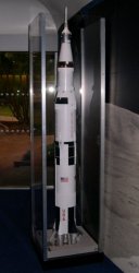
The
finished article about to go into the display case. |
At
home in its cabinet. Note the cabinet is too short! |
Thanks go to the following:-
-
My wife Annette for putting up
with my obsession with “that rocket”
-
Greg Anderson of Ozmods for the
wonderful castings
-
Steve Evans of Hawkeye, for the
spectacular decals he made in such a short time
Stephen
|
|